Intro
This tutorial attempts to cover and clarify the process of
optimizing your V-Ray render settings to get the best possible render
quality and fastest render time for a given scene.
There's often a lot of confusion surrounding the topic of
V-Ray's sampling and what 'ideal' settings are. Many times you'll see
artists adopt the 'Universal V-Ray Settings' of having the Image Sampler
(Anti-Aliasing, or AA) Max Subdivs value set very high (like 50 or
100), and then simply lowering the noise threshold value until the
render becomes clean enough - thinking that it's the best / fastest that
V-Ray can do. But with a bit of understanding of how V-Ray works under
the hood, you can achieve a higher quality result WITH faster render
times - in some extreme cases ranging between
3x faster to
13x faster than the universal settings.
We'll first cover some of the underlying concepts behind how
rendering and V-Ray's sampling works. Then we'll go over an example
scene to demonstrate exactly how a render can be optimized to be faster
and cleaner. Then we'll learn how to identify the different sources of
noise a scene can have. And finally I'll provide a step-by-step
procedure to optimize any scene to render with an ideal balance of
quality and speed.
If you already know the underlying concepts and just want the technical step-by-step procedure, click
here to skip right to it.
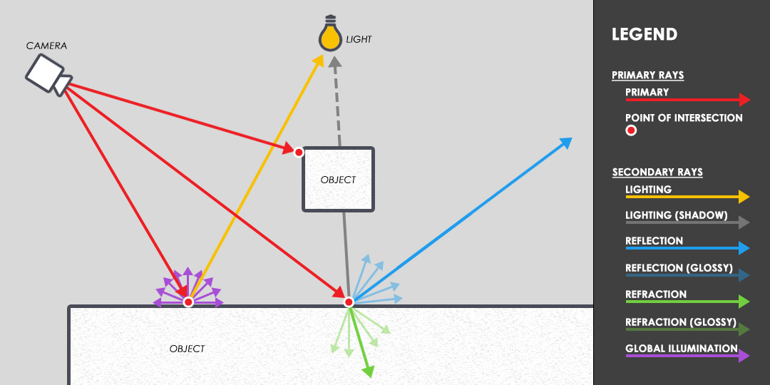
Raytracing 101
When a render begins, rays are first sent out from our camera
into the scene to gather information about the geometry that will be
visible in the final image. These rays originating from the camera are
called
Primary Rays (sometimes also called Camera Rays or Eye Rays) and are controlled by V-Ray's
Image Sampler (Also known as Anti-Aliasing or AA).
Whenever a Primary Ray intersects with geometry in the scene,
additional rays get sent out from that point of intersection into the
rest of the scene to gather information about things like Lighting,
Shadows, Global Illumination (GI), Reflection, Refraction, Sub-surface
Scattering (SSS), etc. These additional rays are called
Secondary Rays and are controlled by V-Ray's
DMC Sampler.
From this point forward, we'll simply refer to 'Rays' as
'Samples' - because that's what the purpose of a Ray is - to take a
Sample of a scene to gather information about what's going on in it.
Rays = Samples.
In order to accurately figure out what's going on in a scene,
many Primary and Secondary Samples are needed to be taken. The more a
scene gets sampled, the more information V-Ray is able to gather about
the scene, and the higher quality the render will be - which means less
Noise in the render. You see,
Noise is caused by a lack of information.
Noise present in a render means that V-Ray wasn't able to gather
enough information about what's going on in a scene. So in order to
reduce noise, you need to provide V-Ray with more information - and to
provide V-Ray with more information, you need to take more samples.
The amount of Primary Samples sent out into the scene is mainly controlled by the
Min Subdivs,
Max Subdivs, and
Color Threshold settings of the Image Sampler. The amount of Secondary Samples sent out into the scene is mainly controlled by the
Subdivs settings from individual Lights / Global Illumination / Materials in the scene, and the
Noise Threshold setting of the DMC Sampler. (
Noise Threshold is named
Adaptive Threshold in V-Ray for Maya)
So to recap the important terms:
| Ray = |
Sample |
| Primary Samples = |
The samples controlled by
V-Ray's Image Sampler (also known as Anti-Aliasing or AA), which is
specialized in figuring out a scene's geometry - as well as textures,
depth of field, and motion blur. |
| Secondary Samples = |
The samples controlled by
V-Ray's DMC Sampler, which is specialized in figuring out a scene's
Lighting, Global Illumination (GI), Shadows, Material Reflection &
Refraction, and Sub-Surface Scattering (SSS). |
| Noise = |
A lack of information. |
| Subdivs = |
The square root of the actual number of Samples. So Subdivs2 = Samples.
For example: 8 Subdivs = 64 Samples. (82 = 64) |
In this tutorial we'll learn how to best utilize these Primary
and Secondary Samples to get the highest quality render (lowest amounts
of Noise) in the fastest amount of time.
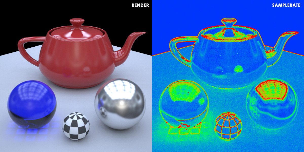
Understanding The SampleRate Render Element
The SampleRate render element is one of the most important
tools we'll be using to help us optimize our renders. It's V-Ray way of
showing us exactly what the Image Sampler (AA) is doing at any given
pixel. It does this by assigning a certain color for each pixel in the
render according to how many Primary Samples (AA) are being taken at
that pixel (which can be seen by viewing the SampleRate render element).
- A Blue-ish color means a low amount of the available Primary Samples (AA) was taken at the pixel.
- A Green-ish color means a medium amount of the available Primary Samples (AA) was taken at the pixel.
- A Red-ish color means a high amount of the available Primary Samples (AA) was taken at the pixel.
So for a scene with the Image Sampler (AA) set to
1min and
10max Subdivs (meaning
1min and
100max Primary Samples):
- A Blue pixel means that 1 Primary Sample was taken
- A Green pixel means that 50 Primary Samples were taken
- A Red pixel means that 100 Primary Samples were taken.
And for a scene with the Image Sampler (AA) set to
1min and
100max Subdivs (meaning
1min and
10000max Primary Samples):
- A Blue pixel means that 1 Primary Sample was taken
- A Green pixel means that 5000 Primary Samples were taken
- A Red pixel means that 10000 Primary Samples were taken.
Example Scene - Understanding How V-Ray Works
For this tutorial, we'll be working with a simple test scene
consisting of: A plane with a few spheres on top, various simple
materials (including diffuse, glossy reflection, glossy refraction, and
SSS), 2 areas lights, and a domelight with an HDRI. Global Illumination
is enabled and set to Brute Force + Light Cache. This scene file can be
downloaded
HERE.
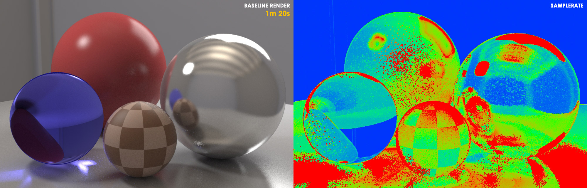
We'll begin with a baseline render with the following render settings:
- Image Sampler (AA) set to 1min & 8max Subdivs.
- Lights, GI, and Materials all set to the default of 8 Subdivs.
- Noise Threshold set to the default of 0.01.
- All other render settings are left at their defaults.
Now lets go over exactly what's happening in this baseline render. Through the render settings, you're telling V-Ray:
"I'm allowing you to use up to 64 (8
Subdivs) Primary Samples (AA) per pixel to figure out what's going on in
this scene and reduce the noise as close as you can to my specified
noise threshold... BUT for each of those Primary Samples you take,
you're only allowed to take 1 additional Secondary Sample to figure out
what's going on for each Light, GI, and Material."
At this point you may be asking:
"Wait, only 1 Secondary Sample for the Lights, GI, and
Materials each? Shouldn't it be 64 Samples (8 Subdivs) as we've set
them?"
Well it's important to note that even though the Lights, GI,
and Materials are set to 64 Samples (8 Subdivs) each - V-Ray internally
divides this value by the AA Max Samples value of your scene.
So
instead of the 64 Samples for the light and material each as you might
expect, this gets divided by the AA Max of 64 Samples (8 Subdivs), which
results in only 1 Secondary Sample being taken for the Lights, GI, and
Materials each. (64 Secondary Samples / 64 Primary Samples = 1 Secondary Sample).
The reason V-Ray does this is because it's internal formulas
are set up in a way that attempts to automatically balance it's two
samplers. The thinking behind this is that with more Primary Samples
being taken of your scene, a proportionally smaller amount of Secondary
Samples are needed to figure out exactly what's happening in the scene
(which we'll soon learn, this isn't always desirable). This balancing
of the Image Sampler and the DMC Sampler can be a bit confusing at
first, but the important thing to take away is this:
Whenever
you increase your Image Sampler (AA) settings, V-Ray tries to
compensate by internally decreasing your DMC Sampler settings. Later on if you're interested in learning more about how V-Rays internal formulas work - you can check out the
DMC Calculator I've coded - but for right now it's not necessary.
So lets get back to the rendering:
V-Ray finishes the render as best as it can manage, but warns you (by the many RED pixels in the SampleRate render element):
"I was NOT able to figure out what's
going on in all of this scene according to the level of quality (noise
threshold) you want it to be at! - A lot of the time I had to use up
all of the 64 Primary Samples with 1 Secondary Sample per Light, GI, and
Material you allowed me to use for each pixel, but it still didn't
provide me with enough information in those areas."
If we take a look at the render - we'll notice that while the
geometric detail (edges of objects) seem fairly clean and defined, there
are indeed noisy areas of the image - specifically noticeable in the
reflections and shadows. So we've got this noisy baseline render, and
we have two options to reduce the noise to meet our desired level of
quality (noise threshold):
| Option #1 = |
Increase AA Max Subdivs
- Let V-Ray take more Primary Samples to figure out the scene - but
again only 1 additional Secondary Sample for the Lights / GI / Materials
each per Primary Sample. |
| Option #2 = |
Increase Lights / GI / Materials Subdivs
- Tell V-Ray to stay at the same amount of Primary Samples - but
instead allow it take more Secondary Samples with each Primary Sample to
better figure out the scene. |
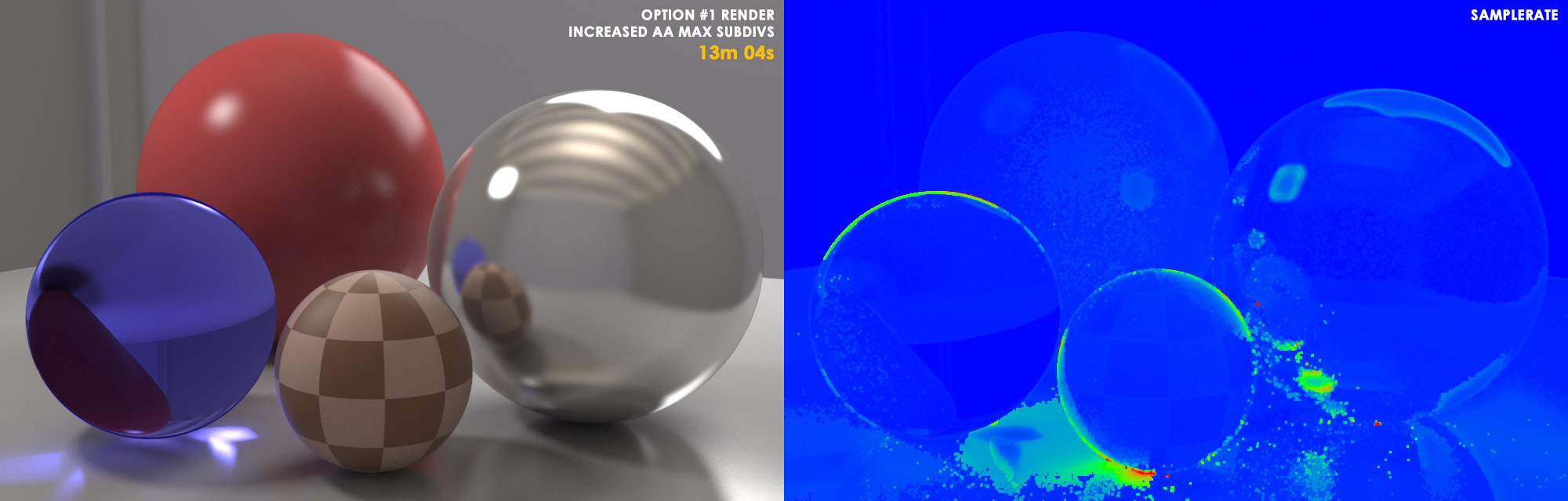
Example Scene - Option #1 - Increased AA Max Subdivs
So lets first try what most people usually do to get a high
quality (low noise) render - adopt the so-called 'Universal V-Ray
Settings' and let V-Ray take as many Primary Samples (AA) as needed to
eliminate the noise.
- We'll increase the Image Sampler (AA) to 1min & 100max Subdivs.
- We'll leave the Lights, GI, and Materials set to 8 Subdivs each.
- We'll reduce the Noise Threshold to 0.005 to tell V-Ray we really want a noise-free render.
Now lets go over exactly what's happening in this Option #1 render. Through the render settings, you're telling V-Ray:
"I'm allowing you to use up to 10000
(100 subdivs) Primary Samples (AA) per pixel to figure out what's going
on in this scene and reduce the noise as close as you can to my
specified noise threshold... BUT for each of those Primary Samples you
take, you're only allowed to take 1 additional Secondary Sample to
figure out what's going on with the Lights, GI, and Materials each."
Again, remember that even though the Lights, GI, and Materials
are set to 64 Samples (8 Subdivs) each - V-Ray internally divides these
values by the AA Max Samples value of your scene. So instead of 64
Samples, this gets divided by the AA Max of 10000 Samples (100 Subdivs),
which results in the minimum of only 1 Secondary Sample being taken for
the Lights, GI, and Materials each. (64 Secondary Samples / 10000
Primary Samples = 1 Secondary Sample).
V-Ray finishes the render as best as it can manage, and tells you (by the now mostly BLUE SampleRate render element):
"I was able to figure out all of what's
going on in this scene to the level of quality (noise threshold) you
want it to be at! - In fact, I was able to figure it out well before I
had to use all 10000 Primary Samples with 1 Secondary Samples per
Lights, GI, and Materials you allowed me for each pixel."
We take a look at the Option #1 render and see the noise has
definitely been improved compared to the baseline render. The render
time has
increased by 11min 44s (9.8x longer) compared to the
Baseline Render, but that's to be expected with a higher quality render,
right? At this point, most people would think this is as good as it
gets, and call the render FINISHED!
...But what happens if we were to try that Option #2 we
discussed earlier? Instead of increasing the AA Max Subdivs, what
happens if we instead opted to only increase the Lights / GI / Materials
Subdivs? Well lets find out...
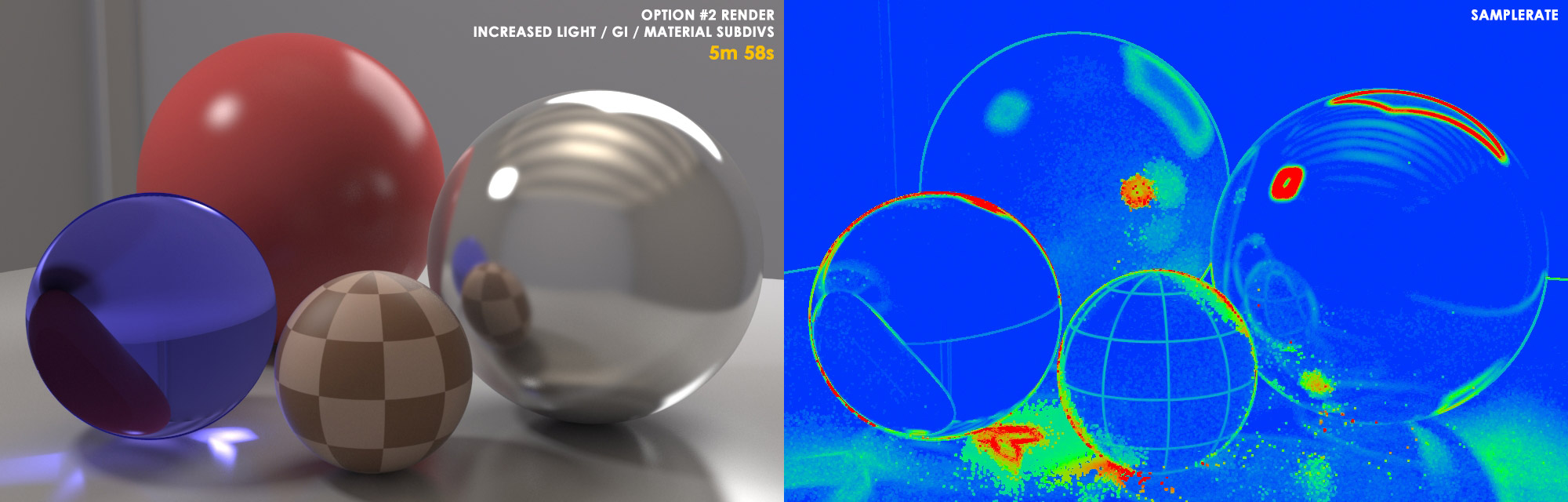
Example Scene - Option #2 - Increased Light / GI / Materials Subdivs
This time we'll try something a little different - we'll tell
V-Ray to take same amount of Primary Samples that we originally did in
the baseline render - but instead allow V-Ray to take more Secondary
Samples with each Primary Sample to better figure out the scene.
- We'll leave the Image Sampler (AA) set to the original baseline render's settings of 1min & 8max Subdivs.
- We'll increase the Lights, GI, and Materials to 80 Subdivs each.
- We'll leave the Noise Threshold set to the original baseline render's default of 0.01
Once more, lets go over exactly what's happening in this Option #2 render. Through the render settings, you're telling V-Ray:
"I'm allowing you to use up to 64 (8
subdivs) Primary Samples (AA) per pixel to figure out what's going on in
this scene and reduce the noise as close as you can to my specified
noise threshold... AND for each of those Primary Samples you take,
you're allowed to take up to 100 additional Secondary Samples to figure
out what's going on with the Lights, GI, and Materials each."
Again, remember that even though the Lights, GI, and Materials
are set to 6400 Samples (80 Subdivs) each - V-Ray automatically divides
these values by the AA Max Samples value of your scene. So instead of
6400 Samples, this gets divided by the AA Max of 64 Samples (8 Subdivs),
which results in only 100 Secondary Samples being taken for the Lights,
GI, and Materials each. (6400 Secondary Samples / 64 Primary Samples =
100 Secondary Sample).
V-Ray finishes the render as best as it can manage, and tells you (through the SampleRate render element):
"I was able to figure out almost
all of what's going on in this scene to the level of quality (noise
threshold) you want it to be at! - In fact, most of the time I was able
to figure it out well before I had to use all 64 Primary Samples per
pixel! All those extra 100 Secondary Samples per Light, GI, and
Material provided each Primary Sample with so much more information this
time!"
We take a look at the Option #2 render and see the noise has
definitely been improved compared to the baseline render. The render
time has
increased by 4m 38s (4.5x Longer) compared to the Baseline Render, but that's to be expected with a higher quality render.
But here's where things start to get interesting...
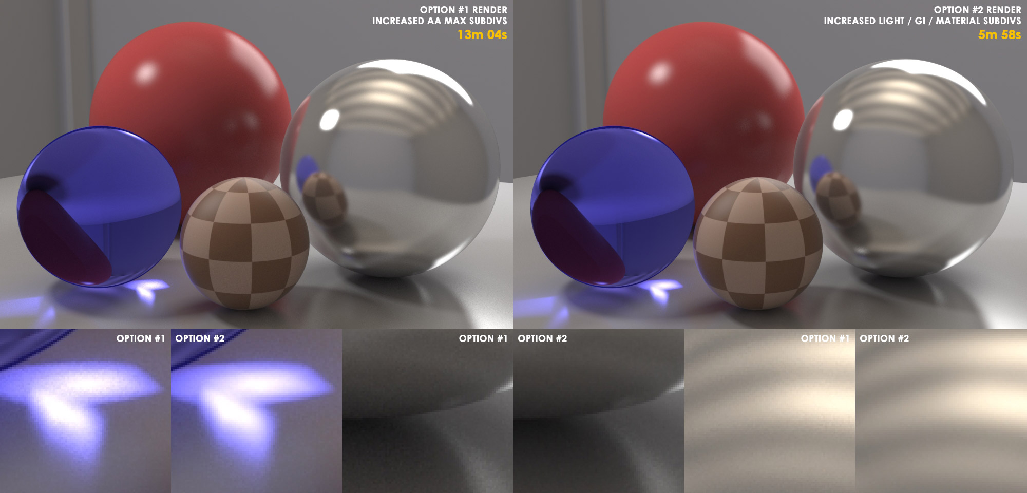
When we compare
Option #2's render against
Option #1's render, we can see that
Option #2 gave us a cleaner render!
And look at that! -
Option #2 finished 2.2x faster than Option #1! -
5m 58s for Option #2 versus
13m 04s for Option #1!
Why is this? Why did increasing the DMC Sampler
settings (Lights / GI / Materials Subdivs) rather than increasing the
Image Sampler (AA) settings result in a
cleaner AND faster render for this scene? We even set Option #1 to have a lower noise threshold, yet it
still turned out noisier than option #2! Well the answer lies in what we originally noticed about the Baseline render...
How Optimization Works
In our Baseline Render, we saw that while the edges of objects
looked clean and defined, the noise seemed to reside primarily in the
reflections and shadows. Well, if you remember what we learned earlier:
Primary Samples (AA) specialize in figuring out
the geometry, textures, depth of field, and motion blur in a scene.
While Secondary Samples specialize in figuring out lighting, GI,
shadows, materials, etc.
So in the case of fixing the noise in the Baseline render, the
choice between Option #1 and Option #2 is actually a no-brainer! Why
use a screwdriver to do a hammer's job? The Image Sampler (AA) had
already done what it was designed to do - make the geometric detail
(edges of objects) clean and defined.
So
instead of firing a bunch of additional Primary Samples (AA) at the
scene to clean up noise - it's better to allocate those additional
samples to the DMC Sampler (Lights / GI / Materials Subdivs) so it can
properly do what it was designed to do - clean up the noise in the
lighting, shadows, GI, reflections, and refractions. There's our
answer!
And now can we begin to understand why the 'Universal V-Ray
Settings' of 1min and 100max AA is generally not going to be the most
efficient method to render a scene -
in fact it never was meant to be the most efficient method!
The Universal V-Ray Settings were designed to make V-Ray accessible
and easy for users who don't care about render optimization or learning
how V-Ray works under the hood. It's simply a method to put V-Ray on
auto-pilot. It allows a user to control all render quality by adjusting
only one setting - the noise threshold. If there's too much noise in a
render, just lower the noise threshold, and V-Ray will keep firing
Primary Samples (AA) at the scene until it eventually reaches the noise
threshold - guaranteeing a nice looking render with minimal
understanding of how V-Ray works. But that render is generally not
going to be as clean or render as fast as if you take the time to
understand how V-Ray works and balance the Image Sampler and DMC Sampler
according to a scene's demands!
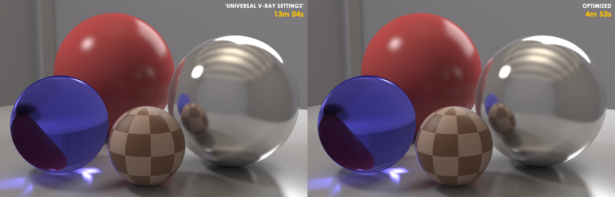
And just to really drive the point home - the Option #2 Render
can still be optimized even further! Using some additional tricks
listed in the procedures at the end of this tutorial, we can reduce it's
render time from
5m 58s to
4m 53s with only a slight hit in noise amounts! For a final render speed increase of
2.7 times faster than the Option #1 Render!
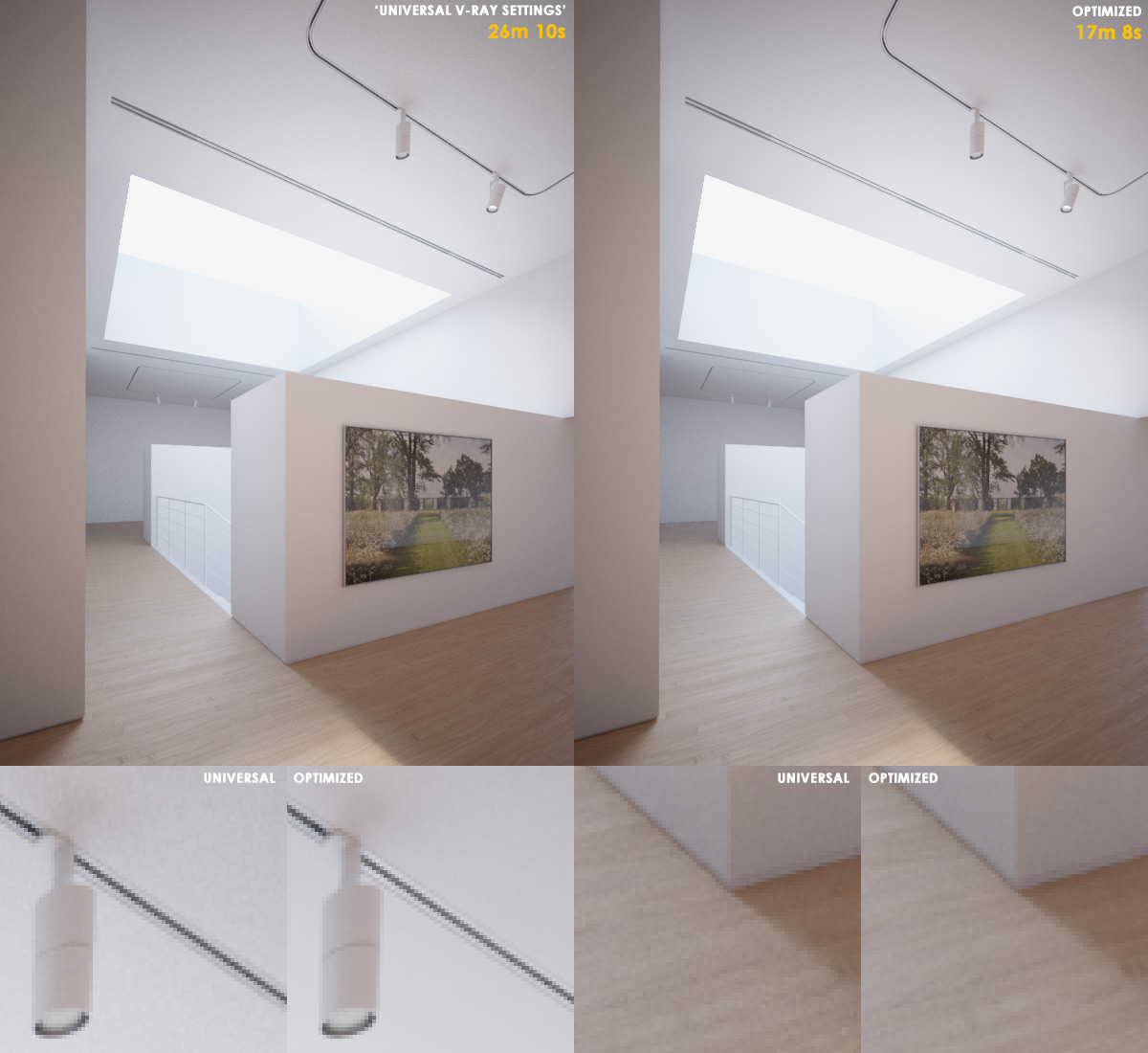
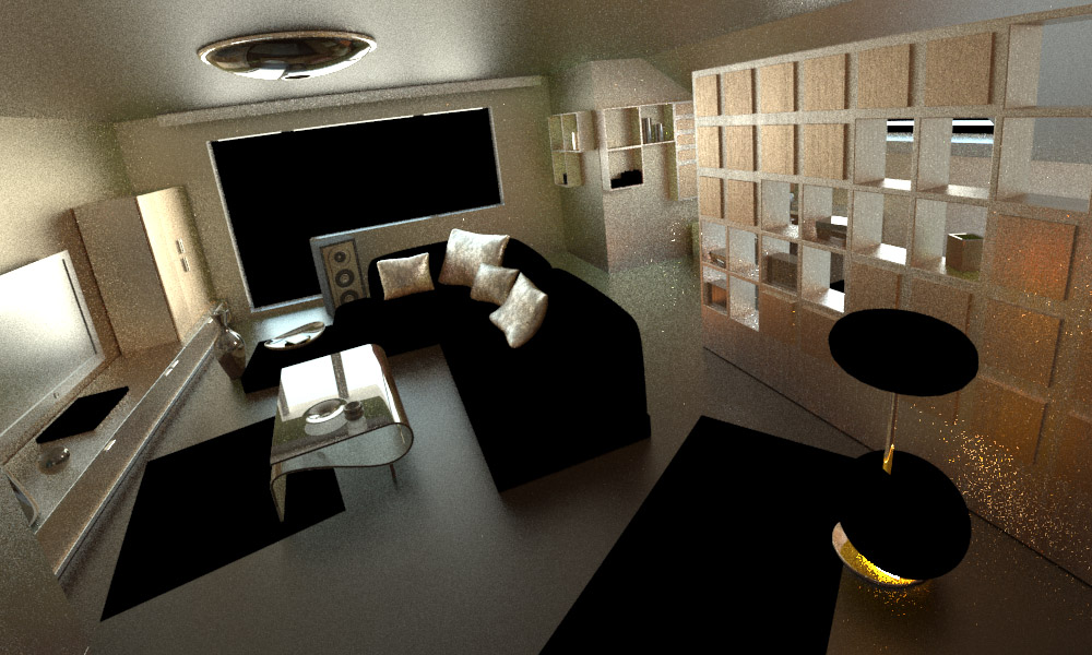
Here's another example of optimization, this time with a more production oriented scene...
The optimized render (right) renders nearly
35% faster
than the universal settings render (left) while reducing noise and
improving render quality. Also note how the reflections have become
more accurate - noticeable on the floor towards the end of the hallway.
Identifying Sources Of Noise
The key to properly optimizing a render is to correctly
identify which aspects of a scene are causing noise, and assigning the
right sampler with enough samples to attack that noise at it's source.
Some scenes will require more samples for the Image Sampler, while
others (like the ones shown in the examples above) will require more
samples for the DMC Sampler. As a general guideline:
Circumstances where the
Image Sampler (AA) will require larger amounts of Primary Samples to eliminate noise:
- Fine geometric detail like Hair, Grass, Foliage, etc.
- Very fine texture detail like weaves, tiny bump map details, etc.
- Scenes with shallow Depth of Field or heavy Motion Blur.
Circumstances where the
DMC Sampler will require larger amounts of Secondary Samples to eliminate noise:
- Large light sources that cast soft shadows.
- Materials with strong glossy Reflection or Refraction.
- Scenes with prominent Global Illumination - particularly indoor scenes.
Noise caused by the Image Sampler (AA) is luckily very easy to
spot to the naked eye. It manifests itself in jagged or unclear object
edges, undefined texture detail or effects like Moiré patterns, and
grainy depth of field or motion blur.
Noise caused by the DMC Sampler can be a bit trickier to see
exactly what's causing it. Luckily we have some handy tools at our
disposal to help us figure it out - V-Ray's Render Elements:
Lighting, Global Illumination, Specular, Reflection, and Refraction.
By looking through these various render elements, you can quickly
isolate and check the levels of noise caused by any of these individual
aspects of your scene.
Additional Tips & Tricks
- In the examples in this tutorial, I kept the Lights / GI /
Materials all at the same Subdivs values for the sake of simplicity and
to make the concepts easy to understand. But it's important to remember
that a properly optimized scene will have varying Subdiv values
specifically tailored to the needs of each of these secondary aspects of
the scene.
For example: A material that's only 5% reflective
probably wont need too many reflection samples to prevent noise from
being visible in the final image, since it's final RGB value will be 95%
dependent on the material's diffuse or refraction components. But if
that same material was instead 95% reflective, it will need more
reflection samples to prevent noise being visible in the final render,
since the reflection will now be the main contributing factor of the
material's final RGB values. The same goes for material glossiness -
the more glossy a material's reflection or refraction is, the more
samples it'll need to eliminate noise. The same applies for lights -
the larger the light, the softer the shadows, and the more samples it'll
need eliminate noise.
- Keep the DMC Sampler's Adaptive Amount setting below 1.0.
There are many instances where setting this value at or near the maximum
value of 1.0 can give really unpredictable results. The default value
of 0.85 is a good place to leave it set.
- Experiment with unlinking the Image Sampler's Color Threshold
value from the DMC Sampler's Noise Threshold by unchecking the 'Use DMC
Sampler Threshold' checkbox under V-Ray's Image Sampler rollout. Then
increase the Color Threshold value in small increments to help the Image
Sampler not confuse noise caused by Lights / Shadows / GI / Materials
for geometric or textural detail. Raising this value can potentially
re-introduce noise in your image, so you can either raise your secondary
Subdivs values higher to compensate, or just accept the slightly noiser
but faster render times. It takes a bit of experimentation to see if
it's worth it for your particular scene.
- Experiment with disabling the Image Filter of the
Image Sampler if you don't have very small repeating detail patterns in
your scene. V-Ray's Image Sampler (AA) already does a good job
resolving and smoothing detail - so additional filtering sometimes isn't
needed.
- Experiment with disabling the Filter Maps checkbox in
V-Ray's Global Settings rollout, or lowering the filter/blur values of
individual bitmaps used in your scene's materials to values like 0.1 or
0.2. Especially consider disabling the filtering of opacity maps for
materials like leaves in trees. Disabling or reducing the filter/blur
values of maps will have a definite render speed increase while making
your maps appear sharper, but can also have the side effects of
increased RAM usage, and possible flickering or scintillation of maps in
animations.
- If using Light Cache for your GI's secondary bounces - enable 'Use for Glossy Rays' and 'Retrace Threshold' to help speed up the calculation of glossy materials.
- If using V-Ray 3.0 - try enabling the Embree raycaster via the 'Use Embree'
checkbox in the V-Ray's System rollout. In many scenes the Embree
raycaster can yield a great reduction in render time with no visible
difference in quality.
- Reduce V-Ray's Bucket Size to something like 32x32 or
24x24 to avoid larger individual buckets getting stuck on a particularly
difficult part of the render while other the buckets finish rendering
and leave the image - causing your CPU to only use a fraction of it's
available power to finish the last bit of the render. V-Ray 3.0
dynamically reduces Bucket Size towards the end of a render to help
avoid this for you.
Conclusion & Acknowledgements
On a closing note - it's important to keep in mind that
every scene is different,
and therefore has different needs from V-Ray's two samplers. Settings
that optimize one scene can potentially grind another scene to a halt -
so please remember:
Your settings and ability to optimize a render can vary greatly from one scene to the next.
With a bit of trial & error, practice, and patience, you can gain
the experience to intuitively know what settings a scene calls for.
So hopefully that helps to clear up the often confusing topic
of V-Ray Render Optimization for you. If you run into any issues, have
trouble understanding something, or have any tips on improving this
tutorial, please feel free to get in
contact with me.
Special thanks to:
Toni Bratinevic and
John O'Connell for the information they've generously shared with the community on the subject.
John Rouse and Nicolas Nandi for their help proofreading and testing the procedures in this article.
Peter Guthrie for lending his gallery scene for use in the examples.
I wish you the best of luck with your future projects!


![[Example]](http://www.cggallery.com/images/tutorials/vray_optimization_procedure_01.jpg)
![[Example]](http://www.cggallery.com/images/tutorials/vray_optimization_procedure_02.jpg)
![[Example]](http://www.cggallery.com/images/tutorials/vray_optimization_procedure_03.jpg)
![[Example]](http://www.cggallery.com/images/tutorials/vray_optimization_procedure_04.jpg)